지난 포스팅까지 Zybo z7-20 보드에 Pcam 5C라는 모듈의 카메라를 연결하여 HDMI로 실시간 영상을 획득했습니다.
2021.05.19 - [Digital Logic/Zybo z7 프로젝트] - [Zybo z7-20 보드 실습] Pcam 5C 영상 출력 (MIPI - HDMI)
[Zybo z7-20 보드 실습] Pcam 5C 영상 출력 (MIPI - HDMI)
프로젝트 컨셉 이번에는 Zybo z7-20 보드로 해보고 싶었던 카메라 Pcam 5C 실습을 해보겠습니다 PCam 5C는 MIPI 통신을 사용하며 보드에 장착되어 있는 HDMI TX 포트를 이용하여 모니터에 촬영되는 영상을
rubber-tree.tistory.com
2021.05.21 - [Digital Logic/Zybo z7 프로젝트] - [Zybo z7-20 보드 실습] Pcam 5C 영상 출력 (OV5640 Register 제어)
[Zybo z7-20 보드 실습] Pcam 5C 영상 출력 (OV5640 Register 제어)
지난 포스팅에서 Zybo z7-20 보드를 통해 Pcam 5C로 영상을 출력했습니다. 2021.05.19 - [Digital Logic/FPGA] - [Zybo z7-20 보드 실습] Pcam 5C 영상 출력 (MIPI - HDMI) PS의 main 코드에 올라와있던 카메라 R..
rubber-tree.tistory.com
대략 그림으로 보면 이렇죠.

이때 카메라의 interface는 'MIPI-CSI'를 이용했으며, 이는 Xilinx에서 오픈 소스로 IP를 제공해줍니다.
2021.05.25 - [Digital Logic/Zybo z7 프로젝트] - [Zybo z7-20 보드 실습] PCam 5C - FPGA Design & IP 분석
GigE Vision IP Core를 찾아서
이렇게 프로젝트 하나를 무사히 마치고 이번에는 Ethernet(GigE) 포트로 GigE Vision 카메라를 구동시켜 보고 싶었습니다.

그래서 이번에도 Xilinx 에서 오픈 소스로 IP를 제공해주나? 하고 봤더니 Sensor to Image 회사(라하고 Euresys라 읽는다)에서 제공을 하고 있더군요.


https://www.xilinx.com/products/intellectual-property/1-8dyf-1824.html
GigE Vision IP Core (GigEVCore2.1)
GigE Vision is a standard communication protocol for vision applications based on the well-known Ethernet technology. It allows easy interfacing between GigE Vision devices and PCs running TCP/IP protocol family. Sensor to Image offers a set of IP cores an
www.xilinx.com
Product Description
GigE Vision is a standard communication protocol for vision applications based on the well-known Ethernet technology. It allows easy interfacing between GigE Vision devices and PCs running TCP/IP protocol family. Sensor to Image offers a set of IP cores and a development framework to build FPGA-based products using the GigE Vision interface. Due to the speed of GigE Vision, especially at speeds higher than 1 Gb/s, senders and receivers require a fast FPGA-based implementation of the embedded GigE core. GigE Vision reference designs supporting speeds up to 25G are available for Xilinx 7 Series, Ultrascale and Ultrascale+ devices.
Sensor to Image 회사에서 IP Core와 개발 프레임워크를 제공한다고 합니다.
Key Features and Benefits
- Control Channel handled by embbeded CPU
- Full functional reference designs for sending (camera) or receiving (host) applications available
- Packet Resend, PTP/IEEE1588 and ACTION command handling in hardware supported
- Implementation of the AIA GigE Vision Protocol
- Hardware Implementation of Stream Channel to reach maximum troughput
- Compatible with Xilinx 7 Series (and higher) and Intel (Altera Cyclone V devices (and higher)
- Compact, customizable
- Speed support from 100 Mb/s to more than 10 Gb/s (1 Gb/s 초과는 FMC 별도 보드 필요)
- Delivered with a full-featured reference design
IP 구성

Top Level Design
The first component of the IP Core is the Top Level Design. It is an interface between external hardware (imager, sensors, GigE PHY) and FPGA internal data processing. We deliver this module as VHDL source code that can be adapted to custom hardware.
Video Acquisition Module
The Video Acquisition Module of the reference design simulates a camera with a test pattern generator. This module is delivered as VHDL source code, which has to be replaced by a sensor interface and pixel processing logic in the camera design.
Framebuffer
The Framebuffer core interfaces to the FPGA vendor specific memory controller. The framebuffer allows frame buffering and image partitioning. This is necessary to implement the GigE Vision packet resend function.
GigE Packet Composer
The GigE Packet Composer sends all data to the Ethernet MAC and implements the high-speed GigE Vision Streaming Protocol (GVSP).
FPGA Integrated CPU
An FPGA integrated CPU (MicroBlaze, NIOS, ARM) handles non-time-critical network and configuration tasks and runs the GigE Vision Control Protocol (GVCP). This software is written in C and can be extended by the customer.
그리고 Sensor to Image에서 권장하는 FPGA 개발 보드가 따로 있습니다.
MVDK development kit 이며 자세한 내용은 아래에서 다뤄보겠습니다.
Custom Configuration
Some parts of the design are delivered as compiled files only (for example the GigE Vision control protocol library), while other parts are delivered as source code. The design framework comes with all the necessary design files and cores, Vivado or Quartus project files. It is configured either as a GigE Vision camera system with an optional CMOS imager, or as an embedded GigE Vision host (receiver). This system is used as a reference design and evaluation board. The reference design uses the Xilinx or Intel development tools (not in the scope of delivery). Sensor to Image MVDK development kit is a flexible evaluation platform for machine vision applications. It supports GigE Vision host and device reference designs and various Enclustra™ FPGA modules with Intel and Xilinx FPGAs.
Euresys - GigE Vision IP Core
이메일 주소를 입력하고 “계정 생성”을 클릭하십시오. 곧 확인 이메일이 도착할 것입니다. 이메일에 있는 링크를 클릭하면 등록하실 수 있습니다. 무료이며 쉽게 이용 가능합니다! 암호에는
www.euresys.com
그래서 Zybo z7-20 보드로 GigE Vision 카메라 연동시킬 수 있나요..?
Sensor to Image 회사에 GigE IP Core 소스를 받을 수 있는 지 문의를 하였고 아래와 같은 답변을 받았습니다.
Zybo z7-20보드는 Ethernet PHY가 ARM system(PS)와 연결되어 있어 사용을 권장하지 않는다.
FPGA PL과 연결되어 있는 Xilinx ZC702 board와 S2I MVDK-ZX5 board를 사용하라.
그 이유는 "To use the fabric(FPGA PL) based IP core, we need to connect the Ethernet PHY directly to fabric pins(FPGA PL), not the ARM/processing system(PS) pins (like with Zybo), where integrated MAC is connected. The reason is that the interconnect speed from the hard block MAC to the fabric is very poor, so it can’t be used for Gbit data transfer between processing system and programmable logic." 라고 합니다.
결국 GigE 통신은 할 수 있으나 1Gigabit의 속도는 보장하지 못한다는 거죠.
PS에서 AXI 통신으로 PHY를 제어할 수는 있지만 위에서 설명한 IP core를 올리는 건 아니기에 이미지 버퍼 문제로 속도가 다 나오지 못하는 듯합니다.
이게 무슨 말이지?
싶을 수 있습니다.
자. 그럼 Zybo z7-20 보드 부터 추천 받은 Xilinx ZC702와 S2I MVDK ZX5 보드까지 하나씩 알아보며 비교해보도록 하겠습니다.
FPGA 보드 분석
Zybo z7-20 board
The Zynq APSoC is divided into two distinct subsystems: The Processing System (PS) and the Programmable Logic (PL). The figure below shows an overview of the Zynq APSoC architecture, with the PS colored light green and the PL in yellow. Note that the PCIe Gen2 controller and Multi-gigabit transceivers are not available on the Zynq-7020 or Zynq-7010 devices.

가장 중요한 개념은 FPGA 칩에는 Processing System (PS)과 Programmable Logic (PL)이 존재합니다.
각 위치에는 특정 interface들이 설계에 맞게 연결되어 있고 PL와 PS는 AXI interface를 통해 서로 간 통신도 가능합니다.
그리고 Zybo z7-20 보드는 위 그림에서 볼 수 있듯이 Processing system(PS) 영역에 GigE가 연결되어 있음을 알 수 있습니다.
하지만 제가 Sensor to Image(Euresys)사에 요청한 GigE Vision IP Core는 PL을 제어하는 소스입니다. 위 보드에서는 GigE가 PL이 아닌 PS에 연결이 되어 있기 때문에 해당 코드로는 동작할 수 없는 것입니다.
그러나 아예 불가능한 것은 아닙니다. 방법이 있죠.
"The current reference design won’t help as it doesn’t use the PS MAC, so this would require a total different architecture. The only thing what you could to on Zybo would be a software based receiver, but I don’t encourage you to do that. Power of the ARM system is simply too weak to do that. You also would have to run Linux on the board."
ARM Process에 Linux OS를 올려서 동작시킬 수 있습니다!
대신 이미지 출력 속도가 떨어집니다. 혹은 packet loss가 나서 이미지가 깨질 수도 있죠.
위 GigE Vision IP Core 구성에서 언급한 Frame buffer와 GigE Packet Composer(GVSP)가 없어서 완전한 데이터 전송은 보장할 수 없습니다.
https://www.xilinx.com/support/documentation/user_guides/ug585-Zynq-7000-TRM.pdf
그래도 할 수 있는 방법이니 한 번 해봐야죠.
다음 포스팅에서는 Zybo z7-20 보드에 Linux OS를 올려 GigE Vision Camera 연결을 해보겠습니다.
그럼 이번에는 추천받은 보드들을 살펴보겠습니다.
Xilinx ZC702 board
https://www.xilinx.com/products/boards-and-kits/ek-z7-zc702-g.html#overview
Xilinx Zynq-7000 SoC ZC702 Evaluation Kit
The Zynq-7000 SoC ZC702 Evaluation Kit includes all the basic components of hardware, design tools, IP, and pre-verified reference designs including a targeted design, enabling a complete embedded processing platform.
www.xilinx.com
이건 Xilinx에서 판매하고 있는 FPGA 실습 보드 입니다.
보아하니 Zybo z7-20 보드 스펙과 별반 다르지 않습니다. ZYNQ-7000 Family를 쓰고 ARM Core도 모델이 같아요.
그래서 기본 보드는 Ethernet PHY가 ARM system(PS)와 연결되어 있습니다.
https://www.xilinx.com/support/documentation/boards_and_kits/zc702_zvik/ug850-zc702-eval-bd.pdf
대신에 FMC interface를 통해 아래 보드를 연결하면 Ethernet PHY를 FPGA(PL)에 연결할 수 있습니다.
(이 말은 즉슨 GigE Vision IP Core 소스를 사용할 수 있다는 뜻 :)
어? 그럼 Zybo z7-20 보드도 FMC interface 이용해서 아래 보드 연결하면 되는 거 아니냐? 할 수 있지만 안타깝게도 Zybo z7-20 보드에는 FMC interface가 없습니다..

아래 사진과 같이 말이죠.

https://www.xilinx.com/support/answers/51616.html
AR# 51616: Zynq-7000 Example Design - GMII Ethernet through EMIOs
Zynq-7000 Example Design - GMII Ethernet through EMIOs
www.xilinx.com
S2I MVDK-ZX5 board
https://www.euresys.com/ko/Products/IP-Cores/MVDK/MVDK
Euresys - MVDK
이메일 주소를 입력하고 “계정 생성”을 클릭하십시오. 곧 확인 이메일이 도착할 것입니다. 이메일에 있는 링크를 클릭하면 등록하실 수 있습니다. 무료이며 쉽게 이용 가능합니다! 암호에는
www.euresys.com
이건 Sensor to Image(Euresys가 인수함)에서 판매하고 있는 FPGA 실습 보드 입니다. 머신비전용으로 만들었다고 홍보하고 있네요.
보아하니 GigE 뿐만 아니라 10GigE(NBase-T), USB3 그리고 CoaXPress 까지 지원을 합니다.
임베디드 시스템에 대한 머신 비전 시장의 기반이라고 볼 수도 있을 것 같아요.
이 보드도 Zybo z7-20 보드 스펙과 별반 다르지 않습니다. ZYNQ-7000 Family를 쓰고 ARM Core도 모델이 같아요.
대신 Ethernet PHY가 2개 있는데 하나는 ARM system(PS)와 연결되어 있고 다른 하나는 FPGA(PL)에 연결되어 있습니다.

결국 정리하면 이렇습니다.
'GigE Vision IP Core'를 사용하려면,
PL과 PHY가 직접 연결되어 있는 FPGA 보드를 쓰거나 FMC interface를 지원하는 보드 써라
그래야 온전한 Bandwidth 1Gbps를 출력하여 정상적인 이미지를 얻을 수 있다.
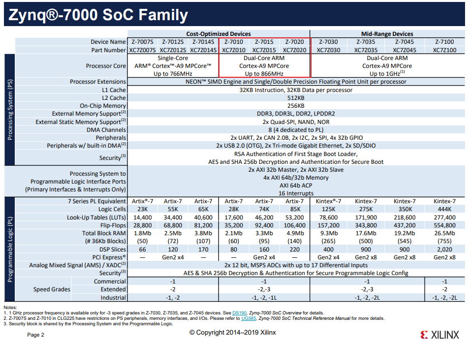
이건 참고로 보드들의 FPGA 및 ARM 정보 입니다.
FPGA chip과 ARM 모델은 거의 유사합니다. 하지만 어떻게 칩 주변의 회로를 구성하냐에 따라 위와 같은 결과를 얻을 수 있는 것이죠.
| Board Model | Xilinx ZC702 board | S2I MVDK-ZX5 board | Zybo z7-20 board |
| FPGA chip | Zynq-7000 family XC7Z020-CLG484-I |
Zynq-7000 family XC7Z015 |
Zynq-7000 family XC7Z020-CLG400C |
| ARM Processor core | Dual-core ARM Cortex-A9 MPCore |
Dual-core ARM Cortex-A9 MPCore |
Dual-core ARM Cortex-A9 MPCore |

https://www.xilinx.com/support/documentation/selection-guides/zynq-7000-product-selection-guide.pdf
'Digital Logic > Zybo z7 프로젝트' 카테고리의 다른 글
| [Zybo z7-20 보드 실습] PCam 5C - FPGA Design & IP 분석 (0) | 2021.05.25 |
|---|---|
| [Zybo z7-20 보드 실습] Pcam 5C 영상 출력 (OV5640 Register 제어) (3) | 2021.05.21 |
| [Zybo z7-20 보드 실습] Pcam 5C 영상 출력 (MIPI - HDMI) (2) | 2021.05.19 |
| [Zybo z7-20 보드 실습] ARM 프로세스 활용하기 - PS (3) | 2021.05.04 |
| [Zybo z7-20 보드 실습] IP Packaging 하는 법 (0) | 2021.05.03 |


댓글